What is a Pipe Flange?
A flange is a plate or ring or form of a rim, welded to the end of a pipe to attach valves, pumps, bends, or other piping equipment to serve the purpose of transporting fluids from point A to point B. Piping components can be bolted together with help of flange. Sealing is often achieved by different types of gaskets.
There are many different flange standards available worldwide. They are designed to make flange interchangeable and functional for its pressure design. The most popular worldwide standards are ASME (USA), AWWA(USA), DIN/EN (European), and BS (British).
What is a Pipe Flange Class?
In the world of pipes and connections, the term “pipe flange class” is like a superhero code that tells us how much pressure a flange can handle. Imagine it as a ranking, like Class 150 or Class 300, where higher numbers mean more strength.
So, when picking a flange for our pipes, we check this class to make sure it can handle the job without breaking a sweat. Think of it as a safety guarantee. Organizations like ASME and ANSI set these standards, making sure our pipes stay strong and steady, kind of like the backbone of a well-built system that keeps everything flowing smoothly.
Click Here for Pressure-temperature Relation Tables
ASME Standards (USA)
ASME B16.5 is a sub-section of main B16 standards that covers steel pipe flanges and flanged fittings from Nominal Pipe Sizes (NPS) 1/2 through NPS 24 for pressure class 150 to class 2500. This is the most common and widely used standard for flanges.
ASME B16.47 is standard for large diameter steel pipe flanges sized from NPS 26 to NPS 60. This standard includes flanges with class rating 75, 150, 300, 400, 600, and 900.
Both standards cover pressure-temperature ratings, material dimensions (Metric/Inch), material compositions, tolerances, marking, testing, and methods of manufacturing.
European (EN/DIN)
Most countries in Europe mainly follow EN/DIN standards of flanges. EN 1092 evolved from DIN 2501 which became part of ISO 7005, then EN 1092 was created as the standard for DIN-based flanges. Various national standards bodies have incorporated this standard into their respective national standards, such as BS EN 1092 und NF EN 1092 etc.
Similar to ASME B16.5, the EN-1092-1 covers different types of flanges, ratings, materials, and dimensions. Their rating ranges from PN 2.5 to PN420.
It is very important to understand that ASME B16.5 & EN 1092-1 are very different standards managed by two different professional entities. They are not interchangeable. Their dimensions of bolt holes and OD are different from each other. Flanges those are from EN1092 standard will not match with corresponding ASME flanges for same pressure range.
Instead of Nominal Pipe Size or NPS, EN use “Diametre Nominal” or DN.
Pressure Class or CLASS(#), EN used “Pression Nominel” or PN.
Types of Pipe Flanges
Despite different standards and dimensions, the most commonly used types of flanges are very similar in all specifications and shapes . Here I list commonly used flanges with a detailed image.
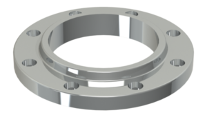
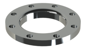
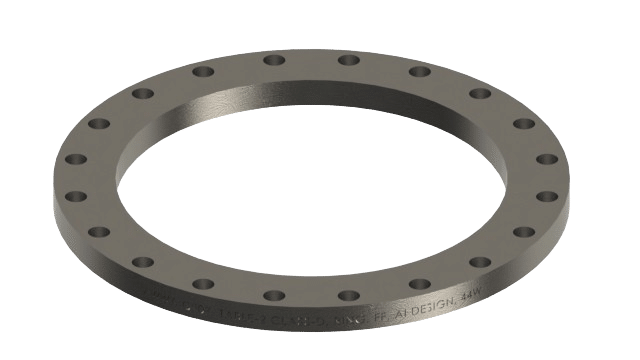
1. Slip-on Flange
Slip-on flanges slide over the outer face of the pipe and are double welded to the face and the cross-section of the pipe & outer face of the pipe. Weld sizes depends on thickness of pipe, hub size and ASME code used to design the joint. Following Images will help understand weld size based on ASME B31.3 code.

Slip-on flanges are very common in low-pressure piping applications. Most slip-on flanges will come with the hub to strengthen it without out increasing extra weight. In some cases, if you have limited space, You can request to remove the hub. This type of flange called “Ring-Type” Slip-on.
On the other side of the hub, Slip-on flanges are equipped with Raise or Flat face. This is face where sealing happens.
Click here for Slip-on Flange Dimensions: ASME B16.5
If you would like to order proper slip-on flanges, typically You need to specify following details:
- NPS size for Flange (EX: 3 NPS)
- Type of Flange (EX: Slip-on FF or Weld-neck RF)
- Pressure Class (EX: Class 150)
- Organization name & Code that covers its specification (EX: ASME B16.5)
- Finally, Material Specification & Code (ASTM A105)
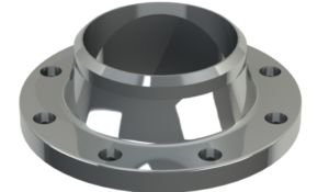
2. Weld-neck Flanges
Weld neck flanges are designed to connect with fitting or pipe with one single butt-weld with minimum transition and resistance in flow. These flanges are bored to match the inside diameter of the pipe or fitting for a smooth transition. this also helps to prevent turbulence and erosion in joints.

As shown in the above image, Weld-neck flanges have a long tapered hub that gradually increased from the pipe connection to the flange face. this tapered hub design gives this flange the ability to withstand higher pressure. it also gives stability under expansion or rapid thermal stress.
Click here for Weld-Neck Flange Dimensions: ASME B16.5
Weld-necks are welded to pipe or fitting with one single V-type butt weld joint. One important thing to remember here, when you order this flange you need to specify Pipe schedule or bore diameter along with all information I have specified in slip-on flange ordering requirements.
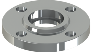
3. Lap-Joint Flange
Lap-joint connection comes in two separate parts, One Loose Lap flange, and another stub-end or backing Ring. A loose lap flange is very identical in look and dimension to a slip-on flange, but instead of welding it directly to the pipe, it should be slid on stub end fitting. Then stub end fitting will be butt-welded to the pipe, so the flange is free to rotate on the pipe co-axial axis.

Lap joints are widely used where flexibility is needed in terms of the rotation of the spool joint. Mostly all compound angle bends and elbows, equipment outlets, and pump intake/outlets are fitted with lap joints.
Click here for Lap-Joint Flange Dimensions: ASME B16.5
As we all know, it is almost impossible to install all equipment and pumps in exact coordination as the drawings created. If you are adding multiple elbows at compound angles or adding a 2 directional spool right after equipment or tank, Lap joints are the only option after grooved fittings.
4. Socket Weld Flange
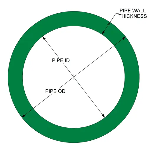
Socket Weld flanges are mostly used on high-pressure piping with a smaller diameter. Pipe ends are inserted in the socket end and apply one pass of fillet weld around the hub side. Its shape is very similar to the slip-on flanges but Socket-weld has a small shoulder inside the bore to match the ID of the Pipe. So that’s why it is important to mention the connecting pipe schedule or wall thickness while ordering Socket-Weld flanges. See the below image for more clarification.

The fitting of this flange required approximately 1/16″ of the gap between the shoulder and connecting pipe. This will allow the pipe to expand during thermal expansion due to temperature changes. If the fitter does not allow the gap, there is a high possibility of cracking inside the pipe.
Click here for Socket Weld Flange Dimensions: ASME B16.5
This gap is also one of the disadvantages of this flange. It causes corrosion problems and crack defects.
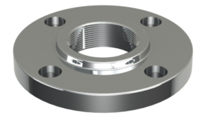
5. Threaded Flange
Threaded flanges are often referred to as NPT flanges or screw flanges. The threaded flange has female taper thread in the center of the bore and the connecting pipe would have a similar size male tapper thread.
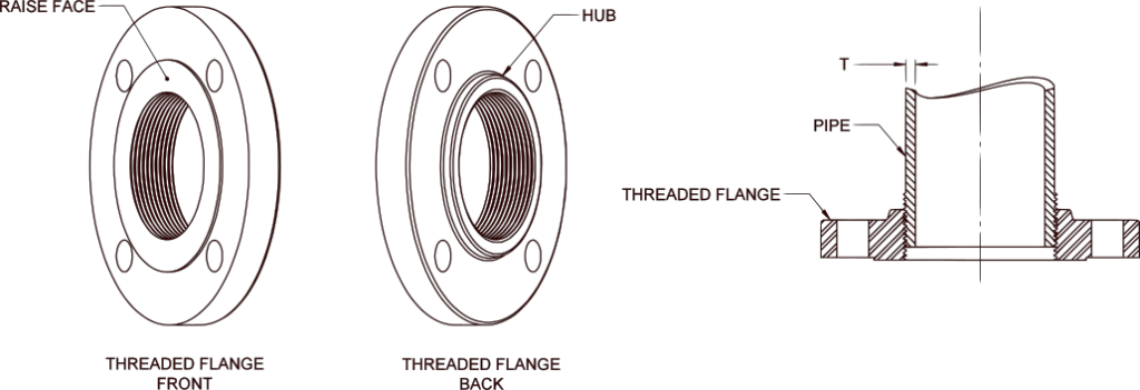
although NPT flanges can be ordered up to 24 NPS, small bores are a better choice for this type of connection. When pipe NPS is smaller than flange NPS, These types of connections are the best choice. I have used these flanges where the spool is attached to the pump or equipment where flange rotations are unknown or hard to derive. Most engineering associations limit the use of threaded flanges ranging from 1/2 NPS to 4 NPS and not more than 300# pressure rating.
Click here for Threaded Flange Dimensions: ASME B16.5
Sometimes I have used these flanges as a threaded connection in the fabrication shop, adjust the orientation in the field and make a full seal weld on the outer face without penetration to gain extra strength and sealing. Try to avoid this connection when you are dealing with thin wall piping.
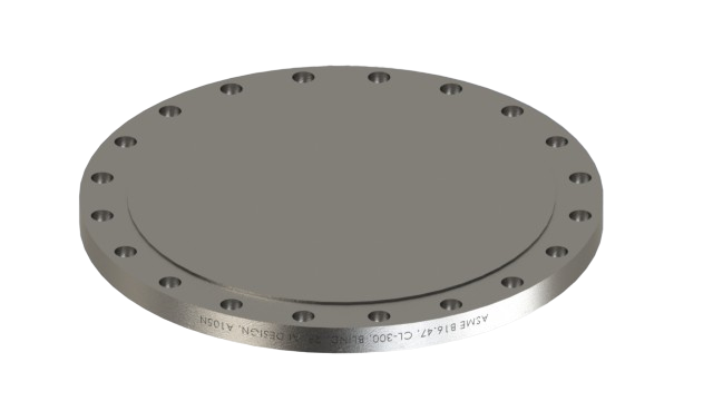
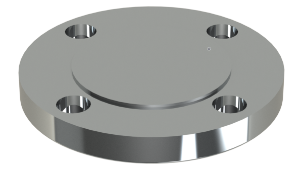
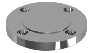
6. Blind Flange
A Blind Flange is a solid plate/disk with no bore at the center. As shown in the image It still has mounting holes as per ASME B16.5 or B16.47. Unlike other flanges, this flange has no opening to allow fluid to pass through. It is primarily used to cap-off pipe ends or nozzles that are auxiliary.
Click here for Blind Flange Dimensions: ASME B16.5
For Process piping and tanks that may have future expansions, It is important to have extra nozzles and branches for new inlets, outlets, or pump connections. Until the next expansion takes place, we need to close this piping with help of Blind flanges. Also, when your hydro testing piping spool or any kind of pressure vessels after fabrication, all outlets must be blocked with blind flanges.

Blind flanges are very often used as the reducer. BF will be drilled to match the OD of the pipe and double welded like slip-on flanges. If the pipe nominal diameter is bigger than the flange, a Blind flange is a perfect choice. I also have seen lots of designs where there are pressure gauges or instruments attached to the end of large diameter branches with help of a Large blind flange bored to 1 or 2 NPS NPT thread and Threaded pipe.